今回のテーマは「交流回路のうち、コイル回路」です。
An AC circuit connected to inductor only
This circuit shows an AC circuit connected to inductor only.
e=Emsinωt・・・(1)
The alternating voltage given by equation (1) is applied to this circuit.
When current i flows in the circuit, the induced electromotive force represented by the equation(2) is generated across the inductor.
eL=-L(di/dt) [V]・・・(2)
■point
The negative sign indicates that the induced electromotive force eL opposes the change in current through the inductor per unit time.The induced electromotive force eL is equal to the applied voltage e.
The formula for them is as follows.
e=L(di/dt)
Emsinωt=L(di/dt) ・・・(3)
Current i flows in this circuit
Rewrite the equation (3).
di=Em/L sinωt dt・・・(4)
Integrating both sides of the equation (4), we will get
i=Em/ωL(-cosωt)=Em/ωL(sinωt-π/2)
The current lags the voltage by π/2
From equation (1) and equation (4),it is clear that the current lags the voltage by π/2.
Em/ωL=XL (inductive reactance)
XL(Em/ωL=Em/2πfL) is called inductive reactance.
Effective values
Current and voltage are expressed as effective values as follows.
I=E/XL=E/2πfL
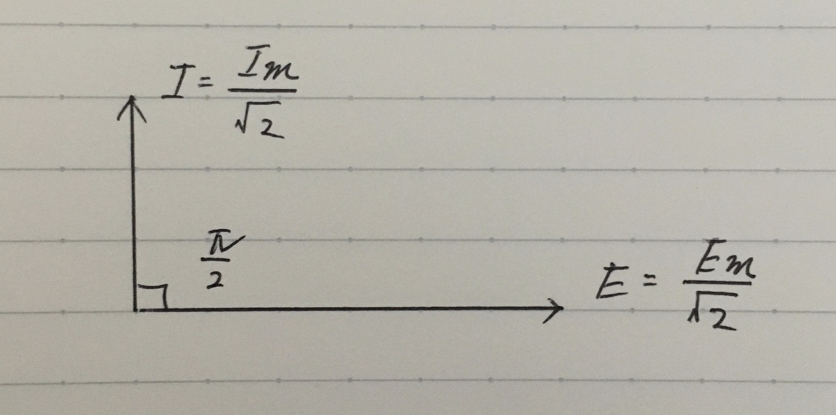
A phasor diagram
A phasor diagram for an AC circuit consisting only of an inductor is as follows.
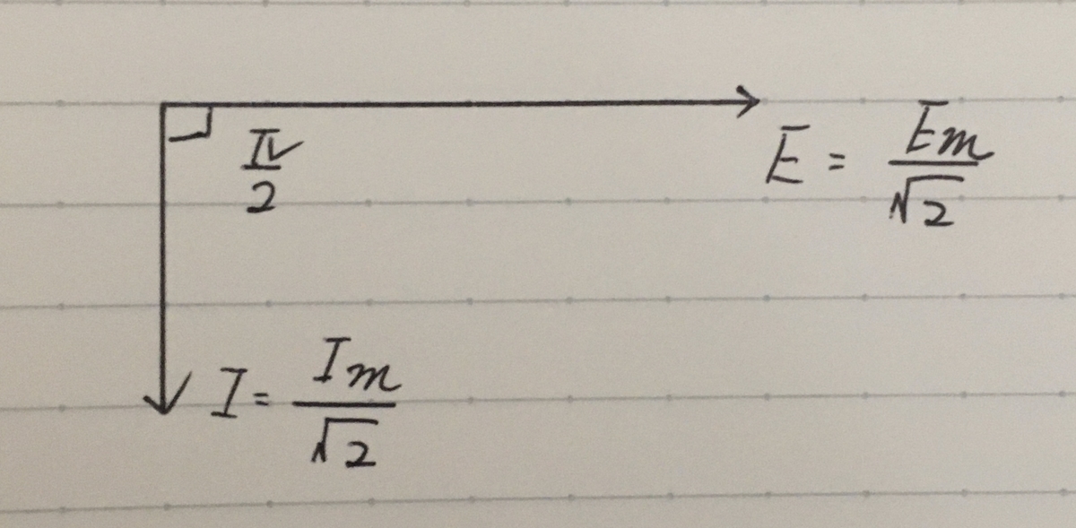
※A phasor diagram for an AC circuit consisting only of an capacitor is as follows.